Monday, October 1, 2012

Printing 3D Model from Revit


Printing 3D Model from Revit


This report will help you to print your 3D model that has been created in Revit. There are few steps that must be taken to make the model ready to print. These steps are illustrated in the following:


1-    Create an appropriate model for 3D printing
There are various types of 3D printers out there. Department of Architecture at Texas A&M University owns “Fused Deposition Modeling (FDM)”. FDM creates models by heating and extruding a filament of plastic material. The 3D printer has a cavity of 8” W x 8” L x 12” H which your model must fit in. The size limitation makes to scale down your model most of the times which result in small parts. But, extremely thin or small parts have a relatively high rate of failure or breakage. Objects that get thinner than about 1/12 inch (2 millimeters) tend to break, or fail to print properly all together. However, the machine can print thin layers with likes sheets and panels pretty well. Figure-1 shows an object printed by the 3D printer at woodshop.


 Figure 1- A 3D model with thin layers printed at woodshop


There is always an option to cut your model into smaller pieces at appropriate sections to be able to print larger models (It is explained later at this document). Figure-2 shows the Revit Family and Revit project of the 3D model. As you can see by exporting the family to project, some of the unnecessary information is removed by Revit. This makes the export of the stl file in next step easier. 


Figure 2 – The 3D model in Revit Family and project


2-    Export a “stl” file format (STereoLithography)
STL files describe only the surface geometry of a 3D object without any representation of color, texture or other common attributes. The STL format specifies both ASCII and binary representations. Binary files are more common, since they are more compact (Burns, Marshall, 1993). Autodesk provides a plugin for Revit that can export Revit model to “stl” file format. You can download this plugin (http://stlexporter.sourceforge.net/) and use it to export your file. Figure-3 shows the exported stl file from Revit which is opened in Rhino to make some modifications.


Figure 3 – Exported 3D model from Revit which is opened in Rhino


3-    Modify the stl file in Rhino and export the final stl
Usually the exported stl files from Revit need some modifications, such as scaling down the whole model to an appropriate size for printing, changing the model’s orientation to minimize the cost, and dividing the large objects to smaller objects to be able to have a larger 3D print. 

Rhino is the best software to modify the .stl file and make it ready to print. Figure-4 shows the same model that the extra parts have been deleted in Rhino.


Figure 4 – 3D model that is modified in Rhino


These are some of the steps that you might have to take in Rhino:
a.    In order to make your model ready to print you need to make sure that you have a closed mesh model. This means that all of the meshes are touching at the corners and there are no unresolved intersections. If you are using Rhino, it has a dialogue box (Figure-5) when exporting objects as a .stl that will inform you when the model is not appropriate for 3D printing.


Figure 5 – Rhino dialog box that shows the model has problem


 If it is not, then you can go back to the original model and attempt to locate problem areas and fix them. Rhino has a plugin to check and repair the mesh for you. You can download the “Mesh Repair” plugin for rhino from the McNeel website (http//wiki.mcneel.com/labs/meshrepair).


Figure-6 shows the Mesh Repair interface for Rhino. As you can see in this figure, the selected object has been checked and it does not have any problem to be exported. 


 Figure 6 – An object that can be exported as a stl file without any problem.


If the selected mesh that you check with mesh repair has a problem, the dialog box informs you about the problem and provides you the option to fix it. As you can see in figure-7, the dialog box provides this information to you:

“Important thing to consider with this mesh:
Mesh has 351 naked edges. Although this does not necessarily mean that the mesh is bad, naked edges can cause problems if the ultimate goal is STL output.”


Figure 7 – Mesh repair dialog box informs the user about the number of naked edges


In order to solve this problem, you can go to the next step in the mesh repair dialog box and fill small gaps. You may need to change the tolerance using the slider to make the number of naked edges to zero and then finish the process. Figure-8 shows this process.


Figure 8 – The process of removing naked edges using mesh repair


b.    Scale down your model to fit in the 8” W x 8” L x 12” H cavity. When you are scaling make sure that the unit of the rhino model is inch. You can make a 8”x8”x12” box and fit your model within. After you finish with scaling, you need to delete the box. Remember that the more of the cavity you fill, the longer it will take to build and the more expensive the print would be.


c.    Make the best orientation of your model which you think minimizes the printing cost and time. This step is similar to minimizing the cost and time of the construction phase of a real project. It is strongly recommended to take two or more options to the woodshop and use the 3D printer software to estimate the cost and then finalize your decision. Figure-9 shows how the model is cut into 3 small pieces to fit in the cavity and also minimize the printing cost.


Figure 9 – The model is cut to 3 pieces to minimize the cost and fit into the cavity


 4-    Print the model
The printing process may take between 2 to 5 days. Usually, the printer prints the model less than 2 days. Figure-10 shows the printing process from 2 different views.


Figure 10 – Printing process from 2 different views


Figure-11 shows the finished printed model from different views. The brown material is the support and the white material is the designed model.


Figure 11 – The printed model that has both the 3D model and support material


After that, it will require at least one or more days in the bath to remove the support material. Figure-12 shows the model after being one day in the hot water bath. As you can see in this figure, the support material is solving in the water and the 3D model shows up clear at the end.


Figure 12 – 3D model after 1 day in the hot water bath

Figure-13 shows the final 3D printed model parts glued together. As it can be seen in these figures, some parts of the model twisted and changed position during the printing process, because they were thin.  


Figure 13- The final 3D printed model
 

Here is the link (http://www.arch.tamu.edu/media/cms_page_media/197/3D_Printer_Information.pdf) that you can find the woodshop document on using the 3D printer and pricing table.


Tuesday, April 24, 2012

Rhino / Grasshopper To Revit - ARCH 689 Project 2

In this project, I have tried to make a real-time link between Rhino /Grasshopper and Revit. There are some limitations exist in accessing Revit in real-time, which delayed the first step of this project. I will provide more documentation about the real-time link in my next post. But, providing link between grasshopper and Revit seems possible and reasonable. In the following I will demonstrate how this link created.

In order to read the geometries in grasshopper, I have created a battery name "ghx2rvt" which gets objects, surfaces, and Breps as input, recognizes their type and creates a "csv" file with the data that Revit needs to create the same geometry using Revit API. To create the geometries in Revit, an application named"ghx2rvt" is created. If the user runs this application, Revit API reads the csv file and creates the geometries in Revit. This program is still under construction and needs more work in the following parts:
  • Create the real-time link
  • Increase the variety of geometries can be exported by grasshopper
  • Increase the variety of geometries can be imported by Revit
  • Providing an application panel which is easy to use in grasshopper
  • Providing an application panel which covers various capabilities in Revit.
The following part provides some detail examples that can be exported from grasshopper and imported to Revit and the process.

A few number of geometries are chosen to be exported from grasshopper to Revit. The first one is "Point" which is the base for all other geometries. ghx2rvt battery has the capability of getting a list of points and create them in Revit. The list of points should be connected to the anyObject input of the ghx2rvt battery. This battery takes the X, Y, and Z coordinate of the point and writes it down on the ghx2rvt.csv file, with the symbol of point. Later when this files is read by Revit API, it can recognize that the object is a point. Figure-1 shows the points, that are result of a surface division, exported to Revit. The user can manipulate this points in Revit.


Figure 1 - Points from Grasshopper to Revit

For creating lines in the Revit based on the respective geometry in grasshopper, I wrote a function in Revit API which takes the end points of the line and creates the line. For each line, the ghx2rvt battery adds a line to ghx2csv battery that has the end points of the line and its symbol. Seeing the symbol of a line, Revit API calls  line function and creates the line. The ghx2evt battery gets a list of line, which can be connected to anyObject input. Figure-2 shows a list of line that is made in Revit based on the existing geometry in grasshopper.


Figure 2 - Lines from Grasshopper to Revit


In order to import circles to Revit from grasshopper, the center point of the circle and its radius is needed. Therefore, these information will be written to ghx2rvt.csv file. Revit API reads these information and creates circles by their center point and radius in Revit.

Figure 3 - Circle (Curves) from Grasshopper to Revit

The process of creating nurbscurves and splines is the same as creating points. Putting each list of curves in an reference point array, gives us an option to create nurbscurves or splines.

Figure 4 - NurbsCurves from Grasshopper to Revit


In order to create surface one step is added to creating nurbscurves. The curves are inserted to a array of arrays. By lofting between these curves the surface an be created.

Figure 5 - Surfaces from Grasshopper to Revit


Using the same methodology, we can create  3D geometries such as Box and Ellipsoid which are shown in Image 6 and 7.

Figure 6 - Box (Extruded Geometry) from Grasshopper to Revit


Figure 7 - Revolved geometry from Grasshopper to Revit


The following video demonstrates that how the ghx2rvt battery can be used. In this video all above-mentioned examples are demonstrated. The video has an case that exports all object at one step to Revit. In this case Revit API separates the objects based on their symbol in the ghx2rvt.csv file and creates them without any problem.


Video 1 - Demonstrates the process of "ghx2rvt" battery

You can download the source code here. See the comments for details and more updates.

Thanks for reading.

Wednesday, March 21, 2012

National Aquatics Center (Water Cube) - ARCH689 Project 1

The Beijing National Aquatics Center (known as the Water Cube) was the main venue for aquatic competitions during the 2008 Summer Olympics. In the design of this building it is tried to make the exterior envelope similar to soap bubbles in water.

The following table provides detail information about this building:

 
Beijing National Aquatics Center
Architect
PTW Architects
Client
Beijing State Asset Management
Location
Olympic Green, Beijing
Total land surface
65,000-80,000 m2
Length
177 meters (581 feet)
Width
177 meters (581 feet)
Height
30 meters (98 feet)
Seats
6,000 permanent and 11,000 temporary
Cost
$140 Million AUD

You can find detail about the design of this building and its characteristics here. Also, Watercube, The Book by  Ethel Baraona Phol provides more information on this building and its energy use and  construction features.

In this project I have used Rhino/Grasshopper to re-create the form of the Watercube in a different way of its original design. You can download the grasshopper file of this model from this link. In the following, I will explain the process of generating the building form in this model step by step.

Developing Model Steps:

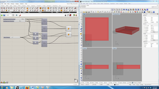
1- In the first step, I parametrically defined different dimensions of the building. I have used two "Box 2Pt" nodes and 3 sliders to create the general shape of the building parametrically. Image-1 shows the nodes.

Image 1 - The parametric model of the building base

2- In order to generate the bubble shapes I have used "3D Voronoi". To use the Voronoi battery, I need to generate some random points. In a building as big as Watercube, to get the bubble size small enough I need a huge number of points. But as the number of points increases the simulation process gets slower and slower. Therefore, I had to find a way to limit the number of the random points. I decreased the number of points by putting some constrains to limit the points to be generated only in the parts that I need them (Walls and Roof of the building and not inside it). In image-2 I have previewed the points on the roof to demonstrate the random point generation.

 Image 2 - Random points on the roof of the building

3- In this step I have used the generated points and boxes in the previous steps. As you can see in image-3, I have used "Solid Difference" node to find the difference of the big box and small box to get closer to the building deign.

Image 3 - "Voronoi 3D" and "Solid Difference" nodes to get the building shape

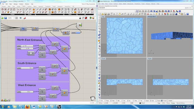
4- In this step I have used "Box 2Pt" and "Solid Difference" to define the entrance opening to the building. Using the sliders shown in Image-4, you can change the size of the North-East, South, and West openings.

Image 4 - "Box 2Pt" and "Solid Difference" nodes to get the building openings

5-This step is the main step in the modeling of the this building. I have used bunch of nodes to get the desired result which I will explain in detail in the following. First, I have exploded the Breps that I have create in the previous step. After decomposing these Breps, I have used the the out-coming surfaces. Using"Polygon Center Pt" I got the center points for each surface, and by "Evaluate Surface" node I could get the normal vector of each surface on its center point.

It is necessary to get exterior surfaces to make the meshes (these meshes are used in the next step to create the bubbles by Kangaroo Physics) and bubble frames. But, exterior surfaces can be extracted for roof and each wall separately. For instance, for roof exterior surfaces, I have found the cross product of the normal of each face and rounded it. The horizontal surfaces would result in "0" and others would result in "1". Then I have used this pattern to "Dispatch" the surfaces. After that, I have found the surfaces that their center points have "Z" value greater that "height of the building -1", which are the exterior surfaces. I have used these surfaces to create the panel frames using"Pipe" battery. Also, I have used "Smooth Mesh" and "WeaverBird's Split Polygon Subdivision" to create desirable meshes for Kangaroo Physics. Image-5 shows these nodes, frames, and meshes for roof of the building. this process would be the same for the exterior walls and the only change would be the vector that is multiplied with the face normal and the comparison values for choosing desired surfaces.

Image 5 - Frames and Meshes of the roof of Watercube Building
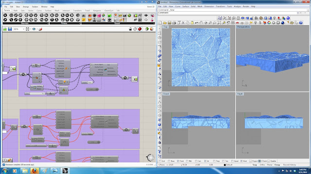
6- This step uses the meshes that are created in the previous step to build the bubble shape using Kangaroo Physics. I have used "Mesh Decompose" node to get the points of mesh vertices. I have put force (which can be changed by a slider) on these points. I have used the "WeaverBird's Mesh Edges"node to get the edges of the mesh and using Kangaroo's "Spring" node, I have prepared all the required inputs for Kangaroo Physics node. Image-6 demonstrates how the force affects the meshes of the roof.


Image 6 - Effect of the kangaroo force on the meshes of the roof of the building

7-  In the design of this building, the designer has tried to create everything based on natural forms of water in nature. the site is designed in a way that it shows the rain drops in water. To model this part, I have used random points again to generate the random rain drops. Using these points and some random radius i have made circles for rain drops. Then each of these circles are extruded. I have made a pipe around each of these small pools to show their boundaries. Image-7 shows the nodes that has been used and the building in the site.

Image 7 - Building site and the rain drop pools on the site

8- The last step of this project is analyzing the result of kangaroo physics. I have used the result of the kangaroo and found the length increase of the mesh edges. Using "Gradient" and"Custom Preview" nodes I have color coded the edges to demonstrate those edges that are under more tension and may  break under physics engine force. Images 8 & 9 show the result of this part under two different forces. Image-8 shows the forces with the force multiplier of "1". In image-9 the force multiplier is "5". As it can be seen, in image-9  more edges are red and yellow comparing to image 8.

Image 8 - Edges color changes based on length change (force multiplier = 1)


 Image 9 - Edges color changes based on length change (force multiplier = 5)


The following video shows how to change the parameters in the grasshopper and their corresponding changes on the rhino file.


I have used Rhino to do the rendering. I will do more rendering using rendering engines and post it later.Image 10 and 11 show the Watercube building rendering results.

Image 10 - Watercube building (Rendered by Rhino)

Image 11 - Watercube building (Rendered by Rhino)


Thank you for reading this post.


Monday, January 9, 2012

Math Nodes for Dynamo

Previously I have talked a little about Dynamo. I thought Dynamo misses some nodes that are very easy to implement, so I have tried to add those nodes. I should mention here that my work compare to Ian Keough is nothing. In his website he invites those Revit API experts interested in visualizing parametric modeling to help him to perfect his work. I am very into it and spend some hours t understand his code and this is the very easy and simple part that I have added.
Using this nodes I have created an example in Autodesk Revit Mass Family. In this example I have taken one more step in creating chair grids. I have used "Math Node Sum" and Math Node Subtract" to define input for reference point grid.


Using Math Nodes In Dynamo


This still has some limitations that needs more work. It only accepts double numbers yet, which a big limitation. I will work on make it capable of accepting both double and integer. I will keep you posted.

Sunday, January 8, 2012

BIM Based Parametric design

These days I am working on Visualizing Parametric Design for Revit. A very good start has been done by Ian Keough. He is working on a Revit add-in named Dynamo. Dynamo is an early exploration into programming for Revit. I have downloaded the source form github and trying to understand the code. In the next step I will add the "Mathematics Buttons" to Dynamo. Math nodes are very easy to implement, yet missing in Dynamo.

For those of you have problem installing Dynamo here is the process:

  1. Go to the github  and download Dynamo
  2. Click on DynamoInstall
  3. Click on Release
  4. Run setup.exe and restart Revit.
I will add a video of the way of installation for the newest version of Dynamo. I will also provide a video that has an example with Math nodes on it soon.

Wednesday, April 27, 2011

Project 2 ARCH653 Revit API - Parametric Design

This project has been designed in four steps:

1) Developing BIM model of Town Hall Building of Alvar Aalto in Revit Autodesk
2) Designing parametric model of fan-shaped truss of the chamber of this building using Revit Interface
3) Developing parametric model of mass of the chamber, fan-shaped truss, and the roof of the chamber using Revit API
4) Developing 4 dimensional model of this project using Navisworks Manager


Figure 1


I have talked about the first two steps in the previous post, so I will discuss the two remaining steps in this post.


Figure 2

As we know in order access the parameters of a model which is parametrically designed in a project we have to use API programming. Therefor in this part of this project we have tried to learn how to control parameters using Revit API.

Figure 3-7 shows how the API program works in this project. After running the TownHallBuilding.dll file through Revit AdsInn, a windows application window pops up and asks about the desired roof angle for the chamber of this building.


Figure3


When the user enters the angle to the project, another window pops up and shows the angle that the user has entered and double check it before making any changes to the project.


Figure4

If the user confirms the angle, the API program will set the new angle to the roof of the chamber, the mass of the chamber, and two trusses that are placed under the roof of the chamber.

Figure5

Figures 6 and 7 show a section of the same model with the same changes using section box.

Figure6

Figure7

The  API code which is developed by C# has 7 main parts:

1)            Declaring Global Variables:

I have defined the roof angle as  global variable. The only issue here was the change of units. Therefore I had to convert the value of the angle which was defined by degree in my parametric design and windows application form interface to radian. This could be done using the following formula:

Angle(Radian) =  Angle Degree * π /180

2)                Initializing and starting transaction with Revit


Figure8

      3)          Getting objects from project:
 
Four objects have been accessed from the project. The mass of the chamber which has been used to make walls and roof of the chamber. The two fan-shaped trusses that have been located bellow the roof of the chamber. The roof of the chamber which the walls of the chamber have been joined to it.

      4)        Getting the parameters of objects:

The angle parameter of all of the above-mentioned objects are obtained form project in these lines of codes.

      5)        Getting values of the parameters


Figure9

      6)        Setting the new values of the parameters of objects

Using windows application form, the user can insert desired angle for the roof of the chamber which is used to update the the values of the parameters.  The angle of the mass of the chamber, roof of the chamber, and angle of the two trusses will be update in these lines of codes.


      7)        Commit the transaction and terminating the API program

 Figure10
 
Problems and Challenges:

I have faced a problem in positioning the two trusses. It was a little strange that each time I have tried to change the location of trusses and then run the API program, the trusses have moved to an unknown location and the base plate of truss members has been separated (as shown in figure 11). In order to deal with this problem each time I had to go to all families and edit the family and upload it again to the project. I have checked the process of  developing the family members and the truss many times, but I could not solve the problem. Please go ahead and post any idea you have to solve this problem.

Figure11

Figure 12

In the video 1, you can find more information about the Town Hall Building and about the process of making the 3D model, parametric model, and using API to control the variables. Also at the end of the movie the 4D model of this project is displayed.