The Beijing National Aquatics Center (known as the Water Cube) was the main venue for aquatic competitions during the 2008 Summer Olympics. In the design of this building it is tried to make the exterior envelope similar to soap bubbles in water.
The following table provides detail information about this building:
Beijing National Aquatics Center | |
Architect | PTW Architects |
Client | Beijing State Asset Management |
Location | Olympic Green, Beijing |
Total land surface | 65,000-80,000 m2 |
Length | 177 meters (581 feet) |
Width | 177 meters (581 feet) |
Height | 30 meters (98 feet) |
Seats | 6,000 permanent and 11,000 temporary |
Cost | $140 Million AUD |
You can find detail about the design of this building and its characteristics here. Also, Watercube, The Book by Ethel Baraona Phol provides more information on this building and its energy use and construction features.
In this project I have used Rhino/Grasshopper to re-create the form of the Watercube in a different way of its original design. You can download the grasshopper file of this model from this link. In the following, I will explain the process of generating the building form in this model step by step.
Developing Model Steps:
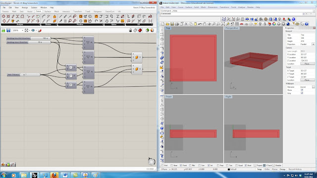
1- In the first step, I parametrically defined different dimensions of the building. I have used two "Box 2Pt" nodes and 3 sliders to create the general shape of the building parametrically. Image-1 shows the nodes.
Image 1 - The parametric model of the building base
2- In order to generate the bubble shapes I have used "3D Voronoi". To use the Voronoi battery, I need to generate some random points. In a building as big as Watercube, to get the bubble size small enough I need a huge number of points. But as the number of points increases the simulation process gets slower and slower. Therefore, I had to find a way to limit the number of the random points. I decreased the number of points by putting some constrains to limit the points to be generated only in the parts that I need them (Walls and Roof of the building and not inside it). In image-2 I have previewed the points on the roof to demonstrate the random point generation.
Image 2 - Random points on the roof of the building
3- In this step I have used the generated points and boxes in the previous steps. As you can see in image-3, I have used "Solid Difference" node to find the difference of the big box and small box to get closer to the building deign.
Image 3 - "Voronoi 3D" and "Solid Difference" nodes to get the building shape
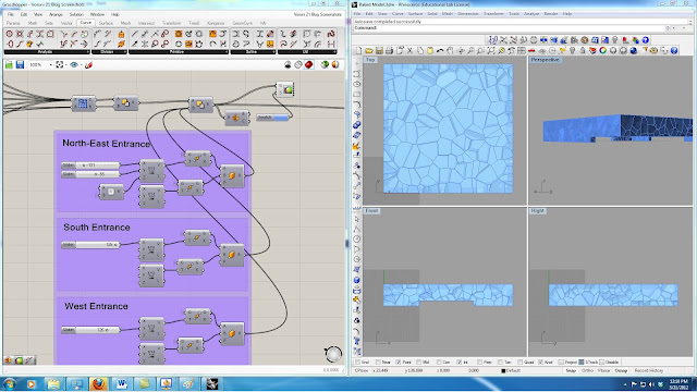
4- In this step I have used "Box 2Pt" and "Solid Difference" to define the entrance opening to the building. Using the sliders shown in Image-4, you can change the size of the North-East, South, and West openings.
Image 4 - "Box 2Pt" and "Solid Difference" nodes to get the building openings
5-This step is the main step in the modeling of the this building. I have used bunch of nodes to get the desired result which I will explain in detail in the following. First, I have exploded the Breps that I have create in the previous step. After decomposing these Breps, I have used the the out-coming surfaces. Using"Polygon Center Pt" I got the center points for each surface, and by "Evaluate Surface" node I could get the normal vector of each surface on its center point.
It is necessary to get exterior surfaces to make the meshes (these meshes are used in the next step to create the bubbles by Kangaroo Physics) and bubble frames. But, exterior surfaces can be extracted for roof and each wall separately. For instance, for roof exterior surfaces, I have found the cross product of the normal of each face and rounded it. The horizontal surfaces would result in "0" and others would result in "1". Then I have used this pattern to "Dispatch" the surfaces. After that, I have found the surfaces that their center points have "Z" value greater that "height of the building -1", which are the exterior surfaces. I have used these surfaces to create the panel frames using"Pipe" battery. Also, I have used "Smooth Mesh" and "WeaverBird's Split Polygon Subdivision" to create desirable meshes for Kangaroo Physics. Image-5 shows these nodes, frames, and meshes for roof of the building. this process would be the same for the exterior walls and the only change would be the vector that is multiplied with the face normal and the comparison values for choosing desired surfaces.
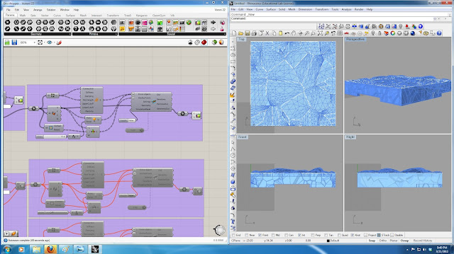
6- This step uses the meshes that are created in the previous step to build the bubble shape using Kangaroo Physics. I have used "Mesh Decompose" node to get the points of mesh vertices. I have put force (which can be changed by a slider) on these points. I have used the "WeaverBird's Mesh Edges"node to get the edges of the mesh and using Kangaroo's "Spring" node, I have prepared all the required inputs for Kangaroo Physics node. Image-6 demonstrates how the force affects the meshes of the roof.
7- In the design of this building, the designer has tried to create everything based on natural forms of water in nature. the site is designed in a way that it shows the rain drops in water. To model this part, I have used random points again to generate the random rain drops. Using these points and some random radius i have made circles for rain drops. Then each of these circles are extruded. I have made a pipe around each of these small pools to show their boundaries. Image-7 shows the nodes that has been used and the building in the site.
Image 7 - Building site and the rain drop pools on the site
8- The last step of this project is analyzing the result of kangaroo physics. I have used the result of the kangaroo and found the length increase of the mesh edges. Using "Gradient" and"Custom Preview" nodes I have color coded the edges to demonstrate those edges that are under more tension and may break under physics engine force. Images 8 & 9 show the result of this part under two different forces. Image-8 shows the forces with the force multiplier of "1". In image-9 the force multiplier is "5". As it can be seen, in image-9 more edges are red and yellow comparing to image 8.
Image 8 - Edges color changes based on length change (force multiplier = 1)
Image 9 - Edges color changes based on length change (force multiplier = 5)
The following video shows how to change the parameters in the grasshopper and their corresponding changes on the rhino file.
I have used Rhino to do the rendering. I will do more rendering using rendering engines and post it later.Image 10 and 11 show the Watercube building rendering results.
Image 10 - Watercube building (Rendered by Rhino)
Image 11 - Watercube building (Rendered by Rhino)
Thank you for reading this post.


